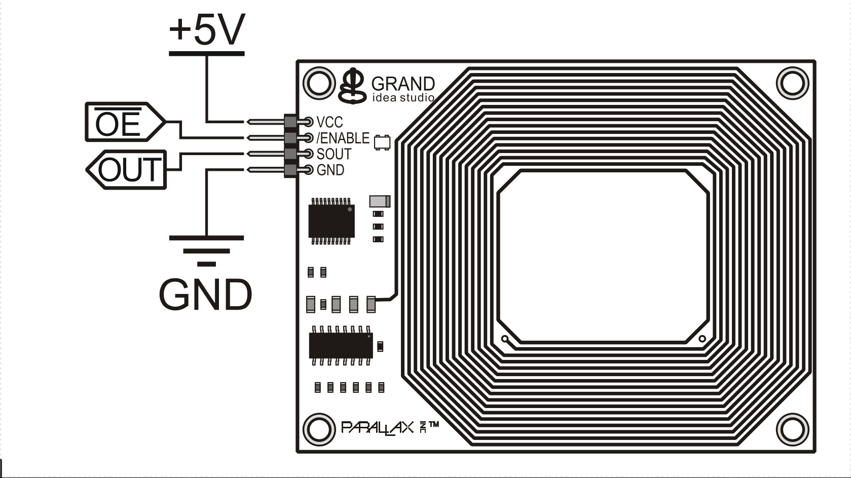
Meant for RFID-reader by Parallax - Product#28140 written in VHDL for Altera FPGA devices.
The reader is connected to the GPIO expansion of the Device. The device for which this driver was written is "Cyclone IV E"/EP4CE115F29C7. For you guys it matters only when cloning the repo and to using the pin-assignments. Take a look at them if you are using a different device.
The User-manual/datasheet for the reader was found here and can be viewed here within the repo, downloaded [here] manual-git-blob.
The reader transmits data in a frequency of 125[khz] through the RFID card and transmits through Sout the data. As described in the manual is shown here:

You can use the GPIO expansion to provide voltage source to the driver and as GND:
The DE2-115 Board provides one 40-pin expansion header. The header connects directly to 36 pins of the Cyclone IV E FPGA, and also provides DC +5V (VCC5), DC +3.3V (VCC3P3), and two GND pins
The GPIO I/O pins can't receive higher voltage than 3.3[V], therefor you must convert Sout's voltage range from 5[V] - 0[V] to 3.3[V] - 0[V] with an external electrical circuit.
Quote from the manual for DE2-115:
The voltage level of the I/O pins on the expansion headers can be adjusted to 3.3V, 2.5V, 1.8V, or 1.5V using JP6 (The default value is 3.3V[..])
I designed and implemented the following design:1

| Sout = 5[V] | Sout = 0[V] |
|---|---|
| VBE = 0.7[V] | VBB = 0[V] = IBR1 + VBE |
| VR1 = Sout = 5[V] = IBR1 | IB ≈ 0 [V] |
| 3.3 [V] = ICR2 + VCE | Transistor is on it's sub-threshold |
| Because both resistors are equal => IC ≥ βIB | IR2 = 0 |
| Transistor is saturated | Sin = VBB = 3.3[V] |
| SIN = VB = 3.3 [V] |
As you can see, there is an inversion for the signal coming out of the reader. Therefor there is a not statement in the design As well as in the pin-assignments.
The broadcast is ASCII codes send as serial output to Sout as described in the Manual:
All communication is 8 data bits, no parity, 1 stop bit, and least significant bit first (8N1) at 2400 bps. The RFID Card Reader Serial version transmits data as 5 V TTL-level, non-inverted asynchronous serial. […], the tag’s unique ID will be transmitted as a 12-byte printable ASCII string serially to the host in the following format: The start byte and stop byte are used to easily identify that a correct string has been received from the reader (they correspond to line feed and carriage return characters, respectively). The middle ten bytes are the actual tag's unique ID. For example, for a tag with a valid ID of 0F0184F07A, the following bytes would be sent: 0x0A, 0x30, 0x46, 0x30, 0x31, 0x38, 0x34, 0x46, 0x30, 0x37, 0x41, 0x0D.
The reader is broadcasting at 2400[bits/sec], therefor it's maximum frequency is 1200[Hz] because you need 2 bits to make 1 cycle. According to Nyquist, The sampling rate should be twice as much therefor it's 2400[Hz]. This is the sampling rate I chose with (created by a PLL by Altera).
According to the communication protocol, There are 10 bits send per byte. There are 2 bytes for the end and start and 10 bytes for the ID itself. Summing up all together leads to 12 * 10 = 120 bits at total in one broadcast.
The sad truth is that In real life there are Errors just like in any other communication protocol and The driver must be able to fix it. The errors that I got and I saw using signaltap2 were extra bits sent randomly during the broadcast, usually 2. I have sort of managed to fix it with the software, but I'll be more than glad to have pull-requests for that section.
I have here a very colorized sampling example of a few samples taken.3

As you can see, Where I've patten red z, it's an error. Besides that, the start bit and end bit are '0' and '1' in conjunction.
Check out the reader.vhd and the case named fixing at line 145.
- I had help from 123d.circuits.com to illustrate it.
- The
signaltapfeature inQuartusenables you to see the actual bits that are sent through the device. It's was extremely useful for me in this development. - You can Access the data via the HTML version or the raw version. You can explore various samples that can be useful for simulation in the samples directory.